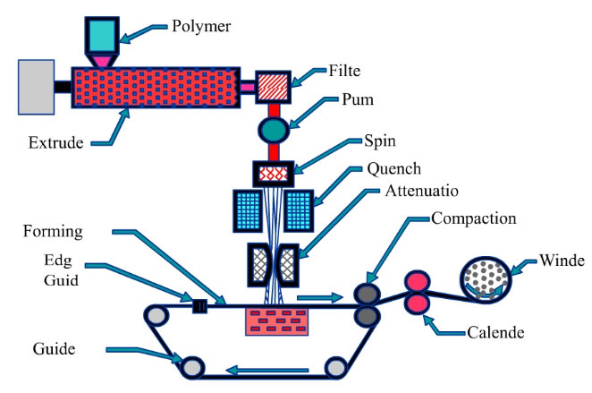
Figure 1. Schematic diagram of the spunbond process From Fedorova, N. (2006). Investigation of the utility of islands-in-the-sea bicomponent.
polymer is melted by heating and mechanical action when it is conveyed to an extruder. It is mixed with stabilizers, additives, color master-batch, resin modifiers, or other additives in the extruder (Nanjundappa & Bhat, 2005). Figure 2 shows the schematic of the extruder. The polymer mixture conveys through the screw and it is melted through the heated screw. Then, the molten polymer moves through the screen (Aipma, 2009).
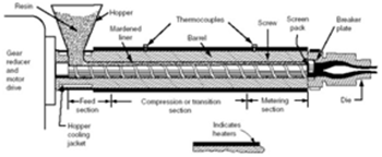
The extruder needs to have a progressive heating and the melt pressure and temperature need to be controlled. Operation pressures and temperatures depend on resin material (Fourné, 1992).
The molten polymer is conveyed to a filter and foreign particles such as metals, solid polymer particles, and others are separated from the molten polymer. The filtering is very important, because the unfiltered polymer may cause problems such as blocking the spinneret holes or creating filament breaks. Then it is conveyed to a metering pump which plays an important role in a precise volumetric flow rate of the molten polymer. The important thing is that once the polymer is melted and liquefied uniform temperature must be maintained to a die block assembly (Wilhelm, Hilmer, & Walter, 2002).
The metering pumps need to be insulated on all sides. The heated temperature is usually in the range of 40kg/h to 100 kg/h and the speed is generally between 10rpm and 40 rpm (Fourné, 1992).
The die block assembly (spin pack) is one of the most important part in the extrusion unit and consists of a polymer feed distribution and a spinneret. The polymer feed distribution needs to control uniform polymer distribution and uniform temperature to keep a balance of the molten polymer flow and the residence time across the die assembly. The molten polymer is conveyed from the feed distributor to the spinneret (Fedorova, 2006).
The spinneret is a single block of metal having thousands of drilled orifices or holes on it, and the designing and fabrication of this part affect web uniformity (see Figure 3).
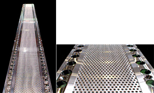
From Kasen Nozzle Mfg. Co., Ltd. (2007). Spunbond Spinnerette. Retrieved from http://www.kasen.co.jp/english/product/line/spanbond.html
To produce a wide web, several grouping of spinnerets called a block or bank is placed side by side to generate sufficient fibers across the total width. In commercial production two or more blocks are used in tandem in order to increase the coverage of fibers (Kasen Nozzle Mfg. Co., L., 2007). When processing two different blends of fibers with different melting points, they must be melted separately and joined in the spin pack or metering pump (Smorada, 2004).
The spin pack is normally designed to withstand 300℃ and 400℃ bar inner pressure over the entire die plate and its temperature needs to be uniformly (Fourné, 1992).
The molten polymer is emitted through the spinneret holes. When the emitted filaments pass through quench chambers, cool air is directed across the filament bundle to cool the molten filaments sufficiently to cause solidification. The quenching can be done by blowing air with either a one sided system or a two sided system. But, with a two-sided inflow quench air supply box, the fabrics can be cooled in a shorter distance than that of one-sided cross flow quench box (Wilhelm, Hilmer, & Walter, 2002).
In the attenuation the filaments are led into a tapered conduit by high velocity air, causing acceleration and accompanying attenuation or stretching of the individual filaments. The attenuation leads to a polymer molecular orientation making up the continuous filament and a modification of fiber diameter (Editorial Staff, 1992a; Wilhelm, Hilmer, & Walter, 2002). The spinning speeds of the process range from 1,000 to 8,000 m/min, depending on the polymer characteristics, process productivity, etc. For example, polypropylene (PP) usually spins at about 2,000 m/min, polyamide spins at about 4,000 m/min, and polyester (PET) usually spins at about 6,000 m/min (Fedorova, 2006).
When quenching using air, other parameters like temperature and humidity must be controlled (Vargas, 1989). The air is the most common method of the attenuation and the take-up rolls or electrostatic method is also used to the attenuation (Fedorova, 2006).
There are generally three spinning methods including melt, dry, and wet spinning for spunbonding. The melt spinning is widely used to spunbonding and there are several systems.
Reicofil system was been developed by Reifenhauser GmbH of Germany. The system is based on the short spin with considerably lower production speeds and lower line capacity. This system is closed system. Many nonwoven companies have licensed this technique from the Reifenhauser GmbH for commercial production (Russell, 2007; Vargas, 1988).
Lutravil system was first developed by Carl Freudenberg Company of Germany in 1965. In the system, the filaments continuously cooled with conditioned air. There are the individual flows of air including primary, secondary, and tertiary air. The primary air and secondary air serve to cool and draw the filaments, while tertiary air serves to take down the filaments in bunches. This system is not available for commercial licensing (Wilhelm, Hilmer, & Walter, 2002; Russell, 2007).
Doncan system was been developed by Lurgi Kohle & Mineral-Oltechnik GmbH of Germany in 1970.
This system is based on a long spinning with a high speed and it requires four floors for production equipment (Russell, 2007; Malkan & Wadsworth, 1992). Many companies have been licensed by Lurgi GmbH and practice this technique (Russell, 2007).
The filaments are deposited on a moving belt. High pressure air through a pneumatic gun is used to move the filaments and a vacuum under the belt helps in forming the filament web on the forming belt. The filaments are separated by mechanical force, aerodynamic force, or electrostatic charge before reaching the belt, to achieve maximum uniformity and cover (Editorial Staff, 1992a). There are some processes: mechanical oscillation, electrostatic charging, slot attenuators, air foils, full-width draw rolls, and centrifugal foaming used for separation and lay down (Gilmor, 1992).
In the mechanical oscillation method, the filaments are separated by mechanical or aerodynamic forces. Figure 4 shows a method and apparatus for producing nonwoven webs patented by Du Pont Company in 1967 and Figure 5 shows a process and device for the manufacture of non woven webs from filamentspatented by Hoechst in 1979.
To uniformly separate the filaments, the filament stream is oscillated by mechanical or pneumatic oscillation of attenuator gun or the filament bundle itself as shown in Figure 4 and 5. Figure 5 illustrates a method that utilizes a rotating deflector plane to separate the filaments by depositing them in overlapping loops; suction holds the fiber mass in place.
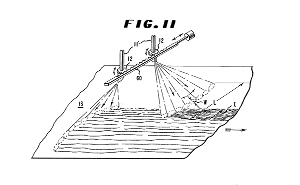
Figure 4. Mechanical and pneumatic filament bundle oscillators From Bundy, R.W. (1967). Method and apparatus for producing nonwoven webs.
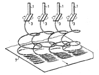
Figure 5. Rotating deflector distribution device From Semjonow, V. & Foedrowits, J. (1979). Process and device for the manufacture of non woven webs from filaments.
The electrostatic charging is one method to spread and separate filaments.
Figure 6 shows a method for triboelectric filament charging patented by Du Pont Company in 1967.
The triboelectric charging is the most common and it is charging via rubbing contact of the filaments with a suitable dielectric material (Kinney, 1967).
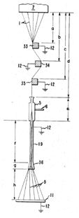
Figure 6. Triboelectric filament charging From Kinney, G.A. (1967). Process for forming non-woven filamentary structures from fiber-forming synthetic organic polymers.
Figure 7 shows a method for corona filament charging patented by Monsato in 1977.
In the corona charging, the filament bundle passes through a corona developed between high voltage electrodes (Sternberg, 1977).
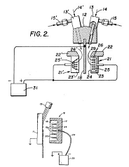
Figure 7. Corona filament charging From Sternberg, E.M. (1977). Method for forwarding and charging a bundle of filaments.
In the slot attenuators, the filaments are put in the moving lay down belt.
Figure 8 shows the slot attenuators patented by Du Pont Company in 1976. Debbes used two rows of narrow slot attenuators covering the full width of the machine. As shown in Figure 8, one row of attenuators had the slots lined up across the web, while the other row had the slots lined up in the machine direction. The two slots are oscillated in the different directions and the filaments are put on the surface of the moving belt in a zig-zag pattern. The result was the fabric with balanced properties in the two directions (Debbes, 1976).
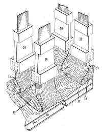
Figure 8. Slot attenuators From Debbes, S.C. (1976). Nonwoven polypropylene fabric.
Many bonding methods can be used to bond the filaments in the spunbond process. These include hydroentangle bonding, needlepunching bonding, thermal bonding, chemical bonding, etc.
The hydroentangle bonding is more complex and expensive, but this technology can produce very different continuous filament structures. This technology helps the tensile strength of the fabrics is improved and the fabrics can be processed at higher line speeds with a higher efficiency (Editorial Staff, 1992a; Smorada, 2004).
The needlepunching bonding provides more comfortable and bulky fabrics than thermal or chemical binder bonding. In the technology, the barbed needles are rapidly passed through the plane of moving spun web (Smorada, 2004).
Thermal bonding is more common and economical than chemical binder bonding. Area-thermal bonding bonds large regions and is based primarily on temperature. Point-thermal bonding, however, bonds small regions and makes use of both temperature and pressure to effect fiber fusion. It is more flexible, since the fibers between the point bonds remaining relatively free (Dahiya, Kamath, & Hegde, 2004).
Chemical binder bonding is used less frequently for spunbond process (Smorada, 2004).